|
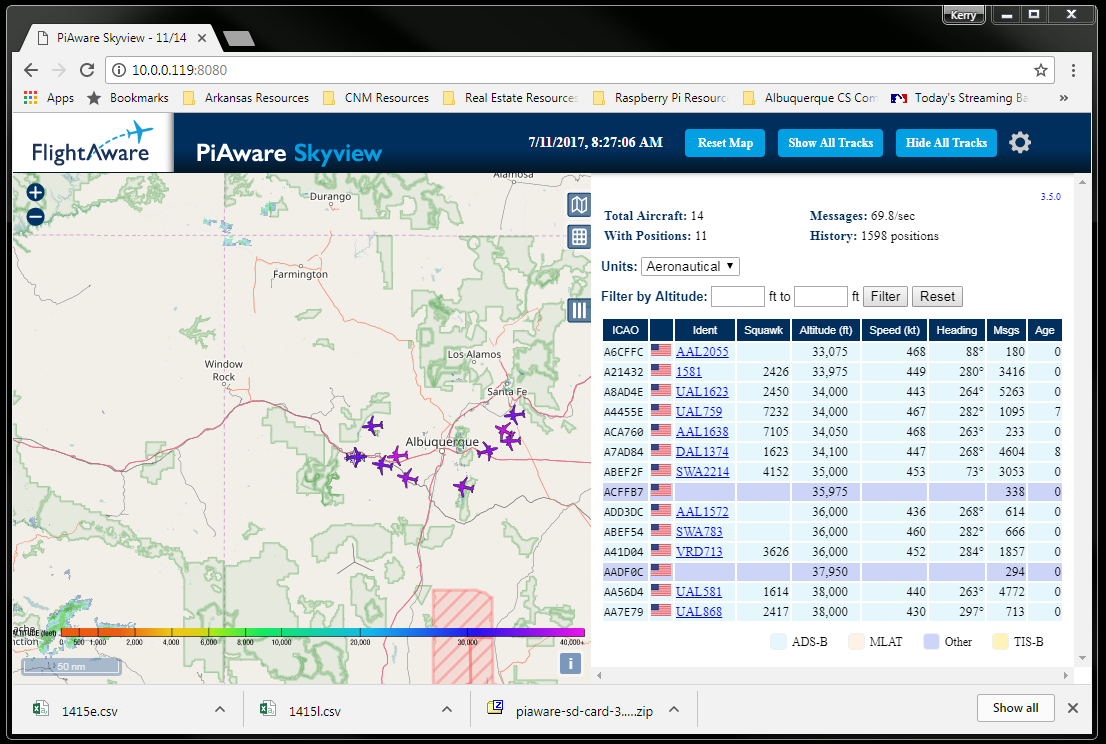
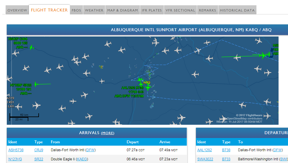
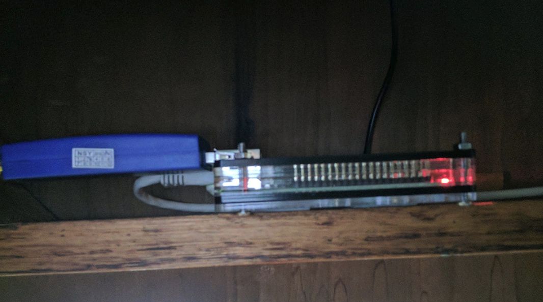
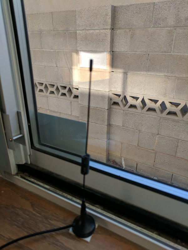
I have my CIS1096 Internet of Things students working on a “mini” project this weekend. So… I thought I would join in on the fun and build a Raspberry Pi based FlightAware tracking system. The build is super simple to get up and running with a small amount of parts needed (See List Below) that cost approximately $75.00. For this project, I used one of my older Raspberry Pi 2 B+ that I hardwired into my home network versus using a Raspi 3 with wireless. The Installation pages provided below are good and have step by step instructions, however, like with most instructions online there was a little bit of modification needed. Main Instruction Page http://flightaware.com/adsb/piaware/ Build a New PiAware Receiver http://flightaware.com/adsb/piaware/build Install PiAware on your Raspberry Pi http://flightaware.com/adsb/piaware/install Update PiAware Software http://flightaware.com/adsb/piaware/upgrade Parts Used for this Project 1 Raspberry Pi 2 B+ (Can use Raspi 3) 1 8 GB SD Card 1 5v Power Supply FlightAware Pro Stick Plus ADS-B USB Receiver with Built-in Filter (https://www.amazon.com/dp/B01M7REJJW?tag=fligh01-20) 1090Mhz Antenna MCX Plug Connector 2.5dbi gains ADS-B Aerial with Magnet Base RG174 1M+MCX Female to SMA male Adapter Connector (https://www.amazon.com/1090Mhz-Antenna-Connector-2-5dbi-Adapter/dp/B013S8B234/ref=pd_bxgy_23_img_2?_encoding=UTF8&psc=1&refRID=35ZFY63Q59R952XCC835) Double Sided tape (to mount Raspberry Pi and Antenna) See My Statistics Here: https://flightaware.com/adsb/stats/user/kerryabruce
0 Comments
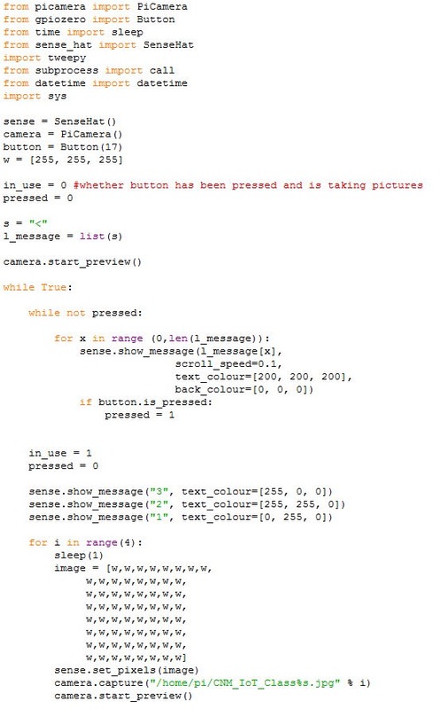
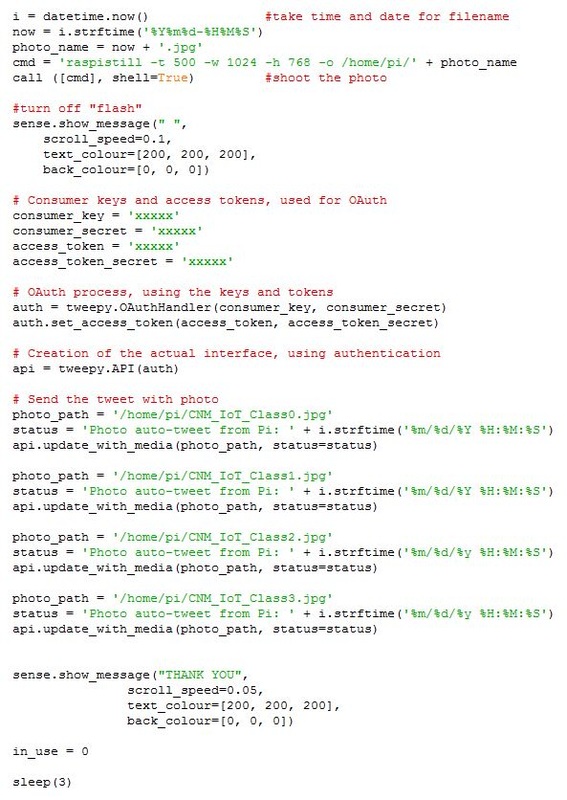
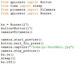
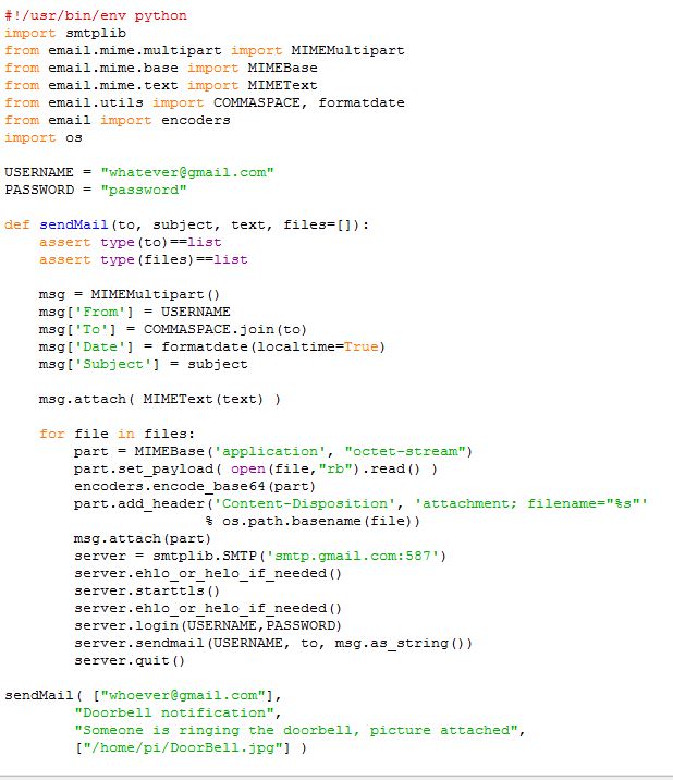
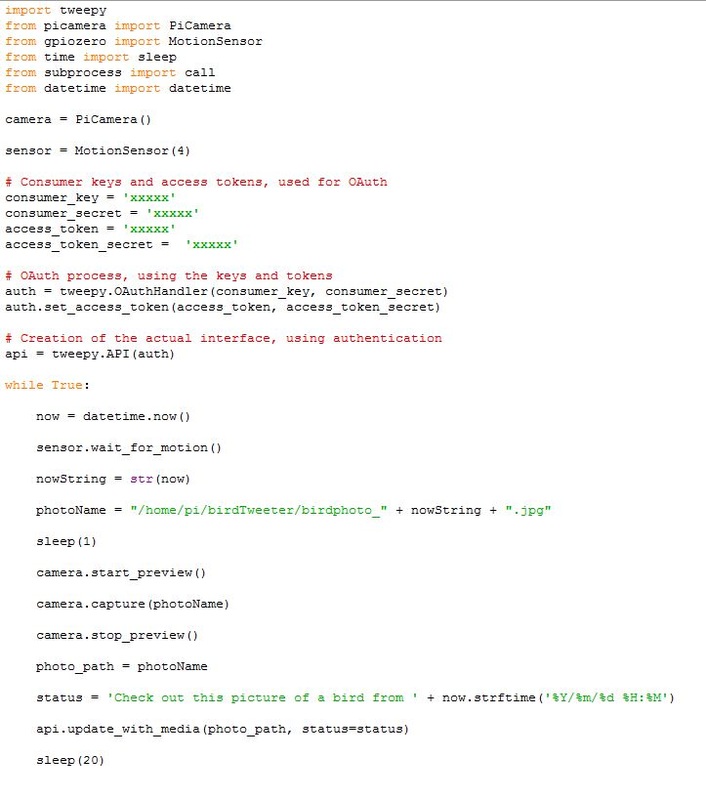
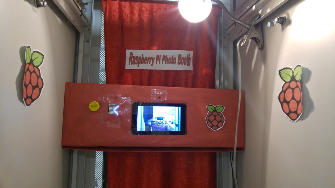 Check out https://twitter.com/CNM_IoT for the pictures from the Photo Booth Twittering Photo Booth Team Members w/contribution to project: Fabian Conant: Using the picamera, sensehat, 7" display created the prototype for our photo booth (in video). Wrote out the script using code from each one of our physical computing worksheets, button, sensehat, picamera. Helped disassemble the server box for the booth, and put together the wood floor inside. Helped with inserts of device box placeholder. Helped with decorations inside and out. Fixed tweepy coding to upload to twitter. James Perea: Found the tweepy script to add for our twitter upload, we worked on the twitter code for hours. He decorated the booth and helped make the custom button. Helped with the disassembly of the server box and he made the curtain hanger for the booth. Keanu Jones: Helped disassemble the server box, helped look for the tweepy script for twitter upload and helped modify the code with loops. He helped with the custom button and decorations of the booth. Alexander Crossland: Helped with dissassembly of server box, helped with decorations, fixed loop problem with button and full script, and pushed for more coding (picamera effects). Brian Frantz: Helped with assembling devices within box holder, helped with fixing loop script. Martha De La Cruz Helped with disassembly of the server box, measured and cut custom box to fit all devices (7" display, sensehat, picamera and all internal wiring) made decorations for inside and out of the booth, helped assemble the final inserts, and helped with original coding on prototype. Contributed with the idea for the project and other ideas such as implementing a countdown and effects for the pictures (due to time we couldn't implement the effects to the photo booth) Project History: On day 1, Thursday, the group and I worked on the (de)construction of the photo booth frame, a former server rack, to empty it out so that it could be stood in. The only things we did not strip from the frame are side panels and a power strip to plug pi components into. Though we stripped one of the doors, we later put it back on so that the booth could only be entered from one side. We decided to fabricate the floor of the booth from scratch out of wood so that it would be safe and sturdy enough to hold the weight of a person. We made sure to take the measurements needed for the floor to fit into the booth frame. We determined that our photo booth would use the pi with a large touch screen, the Sense Hat for its LED array, and a button to press to start taking the photos. The screen would be used to display a preview of the photos. The LED array would display messages, including an arrow pointing to the button, a countdown to the picture-taking, and a thank you message once the photos have been taken and uploaded. Over the weekend, other group members fabricated the booth floor and started the code controlling the pi and its components. Another group member was successfully able to integrate a python library called Tweepy into our python code, allowing photos taken by the booth to be automatically uploaded to Twitter to a specially made account. On day 2, Tuesday, we constructed the cardboard frame and assembled the components of our pi in the frame. In order to have both the touch screen and thesensehat, which normally attach directly to the pi, we added an extension ribbon cable and a board to attach the sensehat and button, then mounted the touchscreen on the pi. With these considerations, we cut out holes in the cardboard frame for the screen, camera, and button. We used a medicine bottle cap to enlarge the size of the button. The cardboard frame's outer dimensions were made precise enough that it did not require additional hardware to mount to the photo booth frame, and simply slid in. I handled the code that was not finished over the weekend, as well as all debugging and code finalization. I was helped by another group member experienced in programming. One obstacle we faced in using one program to control all components was that certain functions of the sensehat and gpiozero libraries basically waited blocked other functions from running at the same time. This resulted in making it difficult for both the sensehat's LED array to display a message, and for the button to wait for input, at the same time. We also had time constraints in mind, as this was the final day for assembly of the project. Though we got around the problem of the button with a loop replacing the waitforpress function, the sensehat's LED message functions caused our code to result in only checking for button input about once every second or so. The solution was to simply write "HOLD" on the button. The code was otherwise completed successfully, and even if the end user misunderstands the "HOLD" message on the button, and continues to hold the button even after the countdown has started, it still appears as if they are using their arm to hold up the camera, as in a "selfie". The actual name of the project was originally "Selfie Booth", rather than "Photo Booth", so I regard this possible misinterpretation as a brilliant accidental feature. We originally also used the LED array at full brightness as a flash for the booth, and though this feature is still implemented, some thought the light to still be too dark, so we also installed an optional lamp in the booth, which can provide constant light rather than a flash. Dark curtains were of course also installed on the photo booth. Resources Used: http://raspi.tv/2014/taking-and-tweeting-a-photo-with-raspberry-pi-part-4-pi-twitter-app-series http://videos.cctvcamerapros.com/raspberry-pi/twitter-api-project-camera-tweet-photo.html https://www.raspberrypi.org/learning/physical-computing-with-python/worksheet/ https://www.raspberrypi.org/magpi/issues/essentials-sense-hat-v1/ Picademy Pi Camera Fun! PowerPoint - See Below http://nodotcom.org/python-twitter-tutorial.html http://videos.cctvcamerapros.com/raspberry-pi/twitter-api-project-camera-tweet-photo.html#program http://support.yapsody.com/hc/en-us/articles/203068116-How-do-I-get-a-Twitter-Consumer-Key-and-Consumer-Secret-key- Final Code Used for this Project Spring 2016 - CIS1096 Group Project (Motion Activated Hummingbird Camera with posting to Twitter)8/10/2016 Hummingbird Motion Sensing Twitter Camera Goal of this Project: To build a motion sensing camera for a hummingbird feeder that post the pictures to twitter. Materials used for this project: Raspberry Pi Pi Camera 7” Pi Touch Display Battery Pack Motion Sensor PIR Jumper cables Twitter Account (See https://twitter.com/CNMBirdTweeter) Code from the working project: Note of the resources used to create the code, including webpages, individuals, classroom worksheets, etc. References for “How to create a twitter app on the Raspberry Pi with Python-tweepy – part 1-4” http://raspi.tv/2013/how-to-create-a-twitter-app-on-the-raspberry-pi-with-python-tweepy-part-1 http://raspi.tv/2014/tweeting-with-python-tweepy-on-the-raspberry-pi-part-2-pi-twitter-app-series http://raspi.tv/2014/tweeting-system-information-from-the-raspberry-pi-part-3-pi-twitter-app-series http://raspi.tv/2014/taking-and-tweeting-a-photo-with-raspberry-pi-part-4-pi-twitter-app-series This is the Python Code for the project. Removed the Consumer Keys and Access Tokens. My name is Kerry Bruce. I am a Computer Information Systems Instructor at Central New Mexico Community College. I created Mr. Bruce’s Hackerspace as a way for my students to explore the world of computers/technology in a fun, cost-effective manner. We use inexpensive development boards like the Raspberry Pi and PCDuino to build interesting projects that spark the imagination and help to increase our understanding of computer systems. I created this website to share our passion and interests with others who share our love for computers, technology, and continued learning. Welcome, I hope you enjoy.
For clarity purposes only. We use the Internet Users’ Glossary (RFC1392) definition of a Hacker to be a person who delights in having an intimate understanding of the internal workings of a system, computers and computer networks in particular. Additionally, from the Oxford Dictionary, we define a Hackerspace as a place in which people with an interest in computing or technology can gather to work on projects while sharing ideas, equipment, and knowledge. For additional information and links to cool projects please check out and LIKE our companion Facebook page at www.facebook.com/mrbruceshackerspace. or click the symbol below! |
AuthorKerry A. Bruce Archives
July 2017
Categories |
- Home
-
My IT Instructor
-
Student Resources
>
-
CNM Courses
>
- CNM - Cisco Self Enroll Courses
- CIS-1410 IT Essentials Hardware
- CIS-1415 Network Essentials
- CIS-1605 Internet of Things
- CIS-1610 IT Essentials Software
- CIS 1696 Introduction to Competitive Robotics
- CIS-2620 Configuring Windows Server
- CIS-2636 Cloud Computing
- CIS-2650 Advanced Windows Server
- CIS-2670 Computer Security+
-
CNM Courses
>
- Instructor Resources >
- NCTC
- Let's Get Social
- Books I Recommend
-
Student Resources
>
- WASTC
- #PiWars Blogs
- Pi IT Up!
- CNM HackerSpace
- Robotics Resources
- Workshop Information

 RSS Feed